| View previous topic :: View next topic |
| Author |
Message |
Burgess
Extreme 3D


Joined: 27 Mar 2012
Posts: 1103
Location: Wales
|
 Posted: Tue Jul 10, 2012 8:17 am Posted: Tue Jul 10, 2012 8:17 am
Post subject: Blade Balancer / Blade Balancing |
 |
|
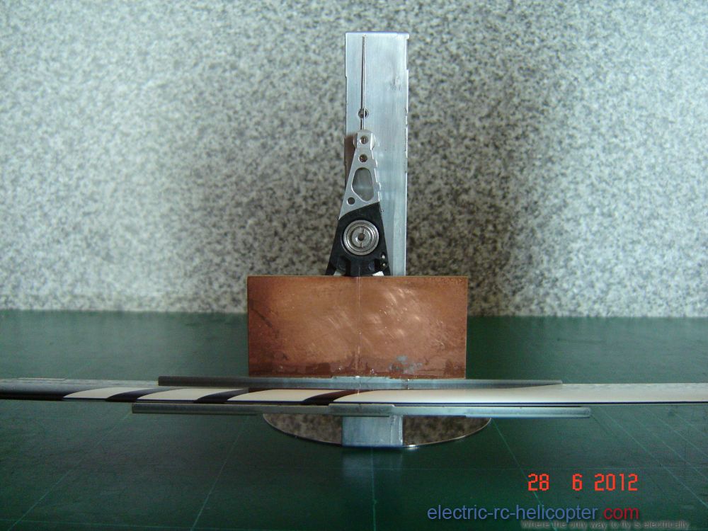
My approach to balancing rotor blades begins with the condition of the blades themselves. There are some good inexpensive carbon fibre and glass fibre rotor blades out there, however, they tend to need a small amount of work to get the best out of them.
i) Primary appraisal: line of sight check, the blades should be dead straight from root to tip, parallel, and camber free. It is pointless to balance a pair of blades if they are not going to be aerodynamically viable.
ii) This part of the procedure will reveal if there is any deviation from dead straight between the root and the main part of each blade and or divergence one from the other, or camber, or warps.
Place the blades side by side and insert a 3mm rod through both pivot holes and clamp the blades together at the roots. The slide-rod from an old CD player make a perfect fit. Take a measurement of the gap between the leading edges and trailing edges, at the root and tip ends of the blades. Release the clamp and swop blades positions clamp and do measurements again, this will reveal the presence of any warps. Release the clamp and remove the 3mm rod.
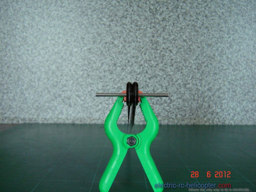
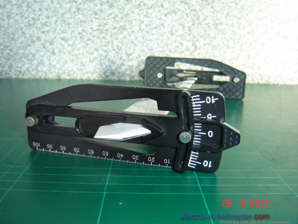
If warps are indicated, fit two pitch gauges back to back on one blade one at the root end and the other at the tip end. Place the assembly onto a flat surface and press down to make full contact with the surface and check where the pointers aline on both gauge scales.
iii) Using vernier callipers measure the thickness of the roots, checking for parallel in the fore-n-aft and span-wise directions. They need to be 5mm. At this point we know wether the blades are good enough to proceed to balancing, or in need of remedial work first.
iv) Some blades have a narrow flat along the leading edge and slight burr either side along the trailing edge. These imperfections are easily rectified with 600 grit wet n dry followed up with 800, or 1000 grit, finish with metal polish.
Blend in the narrow flat along the leading edges to establish a good accurate leading radius without reducing the cord length, as that will change the characteristics of the foil section. The technique I use is to bend the abrasive paper over the leading edge by applying equal gentle pressure use index finger and thumb progress down the full length of the blade with one continuous steady motion. Aim for producing a identical radius dead centre along both blades.
Also, looking down on the blades (plan view), some blades have a slight camber root to tip along the trailing edge(the cord length of the blade is greater at either end than at the mid point, straighten off using a long sanding block to true-up the trailing edges and remove what's left of those burr-edges. Aim to produce a constant thin width down the full length of the blade, and with the 800 grit at 45 degrees gentle pressure to just dull the top and bottom sharp edges. This allows for better boundary layer circulation.
v) Next mark the position for the tracking tape on each blade. Use a sharp H grade pencil and try-square. From the tip of one blade measure in about 25mm and mark with the pencil, use the try square and draw a line both sides of the blade. Place the blades side by side and insert the 3mm rod and clamp the blades together, stand them up on the trailing. Transfer the mark onto the other blade and draw a line both sides of that blade.
vi) Tracking tape: These need to be long enough to rap completely around the blade with an overlap of approximately 6mm. Fold and crease both tapes about 6mm from one end, ease off the backing paper and inboard of the pencil mark, aline the crease on the trailing edge and attach that 6mm end to the underside of the blade, keeping the tape taught rap it around the blade following the pencil-line and overlap the 6mm short end. Using a scalpel, trim off any excess tape.
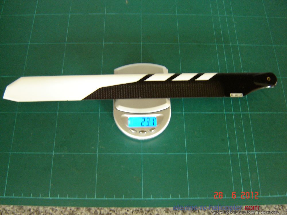
vii) Now weigh each blade and take note of their individual weights; the difference is the potential weight to be added to the lighter blade.
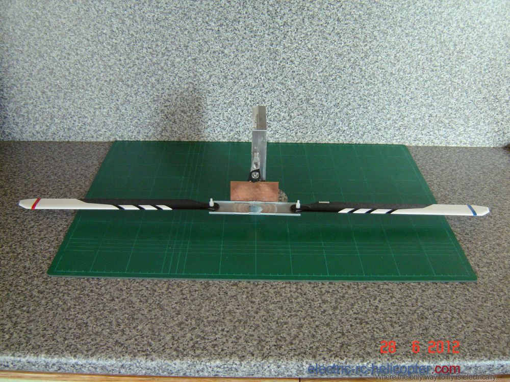
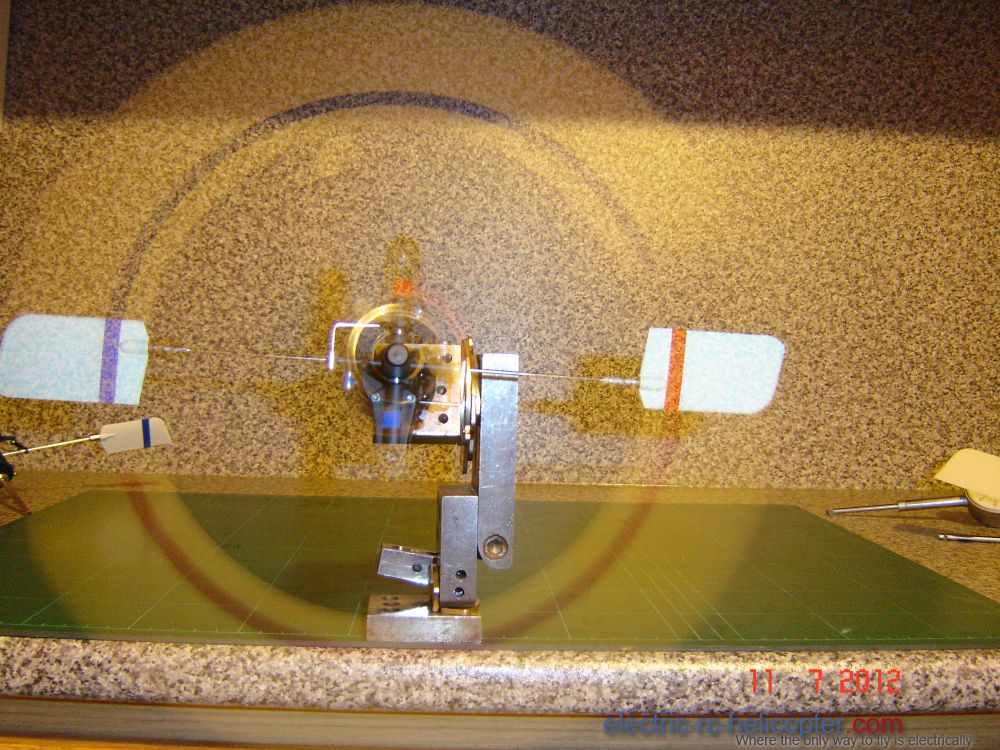
viii) Place the heaviest blade centrally on the cradle of the balancing apparatus, adjust the position until absolute equilibrium is achieved (needle dead centre). Hold the blade steady and mark the CoG location on the blade adjacent to the central index mark on the cradle. Remove the blade from the cradle and with the aid of the try-square draw a line across the blade.

ix) place the blades side by side and insert the 3mm rod through the pivot holes again. Aline the try square with that line on the heavier blade and transfer the CoG index on to the lighter blade. we can now begin to equalise the weights.
I use a heavy duty clear self adhesive tape.
x) cut-off a length of tape that is long enough to rap one round the blade. Place it on the scales adjust the weight to coincide with the weight short-fall of the light blade. Loop the tape back on itself sticky side out.
xi) Place the light blade back on the balancer cradle and align the CoG mark with the central index mark on the cradle. now place the tape loop on the blade towards the light half of the CoG line, finding the correct location by trial and error. When found, mark the blade, then smooth out tape equally from the leading edge back onto either side of the blade at that position.
xii) place blade back on the cradle to verify that the CoG is correct.
xiii) Now secure the blades to either end of the balancer cradle and the index needle should be straight-up at the absolute equilibrium point.
 |
|
| Back to top |
|
 |
silhouette015
Site Admin


Joined: 06 Jul 2007
Posts: 581
Location: Thailand
|
Posted: Tue Jul 10, 2012 1:27 pm
Post subject: |
|
|
Wow what a great post! I hope you don't mind that I splited the post and made it its own topic. I don't think such a good writeup should be at the end of an old thread 
Thanks!  |
|
| Back to top |
|
|
tombo242
Admin

Joined: 04 Nov 2008
Posts: 4718
Location: Santo Estêvão, East Algarve, Portugal. Now 82, but still feels 22.
|
Posted: Tue Jul 10, 2012 8:06 pm
Post subject: |
|
|
Nice post Burgess,
Fills in the gaps on mine, but does involve buying more gear.
Tom. |
|
| Back to top |
|
|
Burgess
Extreme 3D
Joined: 27 Mar 2012
Posts: 1103
Location: Wales
|
Posted: Wed Jul 11, 2012 4:43 am
Post subject: |
|
|
Thanks Tom,
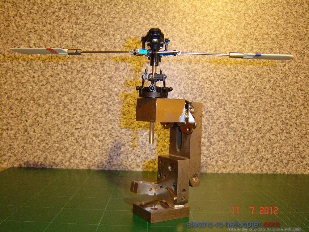
The balancer is made from an unused computer hard drive. I Made this as a get-by when first starting with helis.
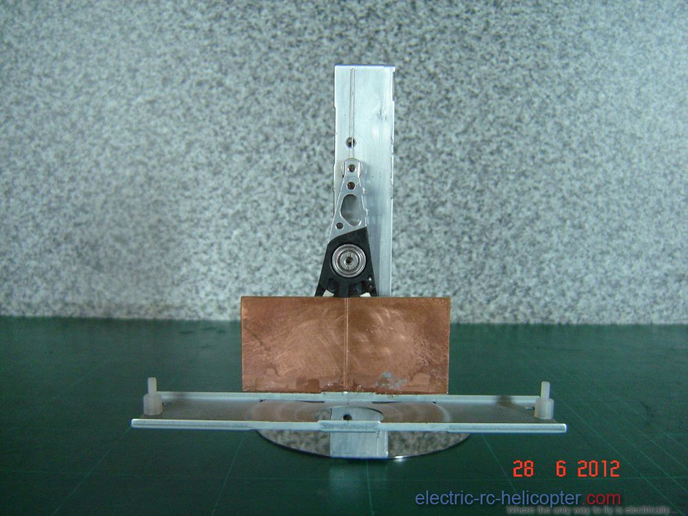 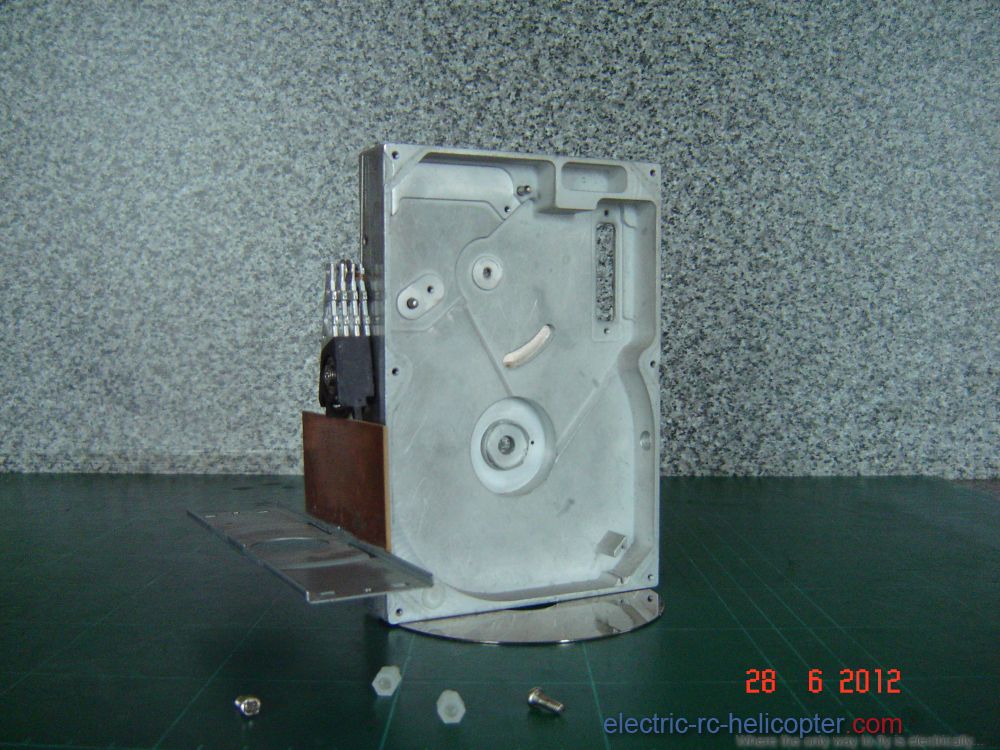
Remove the brushless motor (might come in for something)
Remove the magnet ( I’ll show what they can be used for in another post)
Use one of the platters for a stand fix to one end with double sided tape.
Use the arm for the pendulum (they have very good ball-raced radial bearings fitted).
A rectangle of copper clad electronic board,
The cradle is the upper bridge piece from an old CD player,
Two M2.5x8mm machine screws and two plastic mother board stand-offs,
Short length of piano wire for the pointer.
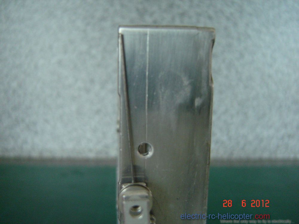
Scribe a line down the front to intersect the screw holes, this is the point of balance line.
Super glue the copper clad board centrally onto the coil end of the arm
stick the CD bridge centrally onto the copper clad board. |
|
| Back to top |
|
|
tombo242
Admin
Joined: 04 Nov 2008
Posts: 4718
Location: Santo Estêvão, East Algarve, Portugal. Now 82, but still feels 22.
|
Posted: Wed Jul 11, 2012 5:25 am
Post subject: |
|
|
Very nice bit of recycling there Burgess, just my style.
Thanks for posting that useful bit of info.
Tom. |
|
| Back to top |
|
|
Burgess
Extreme 3D
Joined: 27 Mar 2012
Posts: 1103
Location: Wales
|
Posted: Wed Jul 11, 2012 8:20 am
Post subject: |
|
|
These harddrive magnets hold things together:
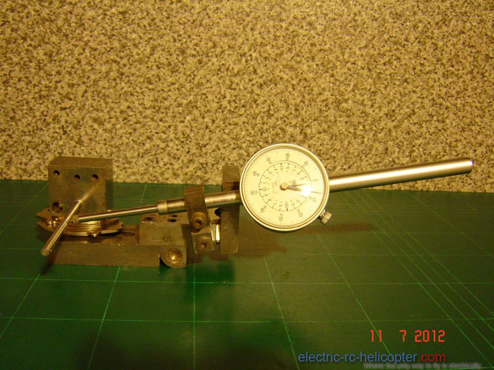
Here’s my apparatus for working of rotor heads, tail rotors, and shafts. It’s another piece of equipment made by recycling stuff I already had. It consists of reconfigured components from an adjustable mounting bracket I made in the 1980s for progressively opening valves to precise settings and holding a TDI gauge to measure the valve opening while gas flowing cylinder head ports on my Super Flow flow-bench.
The top two magnets are as they come out of the harddrive still attached to their mounting plates. The plates must face each other for this to work. this provides a semi-permanent means of holding the top block to the upright, while permitting rotation so that the top block can be turned to any convenient angle while working on a rotor head.
The top block has two 5x10x4mm ball-raced radial bearings fitted.
The base plate is held to the up right by another harddrive magnet which has been removed from it’s mounting plate. The base plate has 3x6x3mm ball-raced radial bearing fitted for checking for run-out in 3mm shafts
The side arm is the clamp for the TDI gauge.
Burgess |
|
| Back to top |
|
|
tombo242
Admin
Joined: 04 Nov 2008
Posts: 4718
Location: Santo Estêvão, East Algarve, Portugal. Now 82, but still feels 22.
|
Posted: Wed Jul 11, 2012 4:04 pm
Post subject: |
|
|
Very neat - I like it!
Tom. |
|
| Back to top |
|
|
Perez Turner
Hover Master

Joined: 05 Aug 2013
Posts: 8
|
Posted: Mon Aug 05, 2013 12:27 pm
Post subject: |
|
|
|
Thanks you so much "Burgess" for sharing to this useful and informative post. You did good efforts and provide much knowledge for newbies to take interest and to solve their problems. |
|
| Back to top |
|
|
Burgess
Extreme 3D
Joined: 27 Mar 2012
Posts: 1103
Location: Wales
|
|
| Back to top |
|
|
solentlife
Extreme 3D

Joined: 30 Dec 2010
Posts: 932
Location: Latvia / UK
|
Posted: Mon Oct 28, 2013 2:15 pm
Post subject: |
|
|
Shaft checking ...
Sometimes you cannot actually see a bend or deformation of a shaft ... but in use you soon see the head 'button' doing its circle !!
Put the shaft into a normal drill and spin it up - even tiny offset becomes obvious to the eye. Test both ends fitted to drill ..
The usual test is on a plate glass or fine table top ...
Nigel |
|
| Back to top |
|
|
Burgess
Extreme 3D
Joined: 27 Mar 2012
Posts: 1103
Location: Wales
|
Posted: Tue Oct 29, 2013 7:37 pm
Post subject: |
|
|
Well, the engineering principle of the shaft gauge is sound, with zero clearance between the gauge and shaft, nothing other than dead straight ought to pass right through the gauge. From the ‘roll on plate glass' test in that video, the distortion of one shaft wasn't that discernable, however, it was immediately evident with the gauge.
I use a test rig with ball-raced radial bearings and a test dial indicator, easy to see a runout of less than 1thou; a runout of 1 thou will produce vibrations.
The drillings on cheep CNC rotor housings can be out of true. So, it's best to check the bear shaft for runout, then check the assembled shaft and rotor housing are concentric. Then check the assembly for dynamic balance at each progressive stage of assembly, especially so with fly-bared heads.
If the rotor head assembly emits a modulating tone/frequency when spooling up and or down, something is out of balance. Extract the head assembly and check the main shaft for eccentric wear marks from contact with the main bearings and that will indicate where to look.
Burgess |
|
| Back to top |
|
|
|
|
|
You cannot post new topics in this forum
You cannot reply to topics in this forum
You cannot edit your posts in this forum
You cannot delete your posts in this forum
You cannot vote in polls in this forum
|
|
|


